Solutions

Experienced engineers will help you intelligently select or customize the proper size and type of screen to meet the demands and rigid specifications in today's material processing plants. The simplest way of acquiring this information is to complete a screen questionnaire. After this information is submitted a Symons engineer will review the application and work with you to determine the type and size of screen best suited for your duty.
Variables
Many materials look alike but will separate somewhat differently. The general characteristics of a material determine its rate of passage through a given hole. Some materials have characteristics that cause them to fracture at a critical size due to their grain structure. If the bulk of the material fractures at a critical size near the dimensions of the screen surface opening, it is difficult to separate. On the other hand, some materials are more friable and have a tendency to break up in quantity to a fine size which makes separation much easier.

A separate calculation is required for each deck of a multiple deck screen, but the same formula is used in each calculation. The successions of unknowns that must be established before using the formula is as follows:
Basic Operating Conditions
- Feed to screening deck contains 25% oversize.
- Feed to screening deck contains 40% half size.
- Feed is granular free-flowing material.
- Material weighs 100 lbs. per cu. ft.
- Operating slope of screen is inclined Screen 18°-20°
- Flow rotation Horizontal Screen 0°
- Objective Screening Efficiency - 95%
| Factor U - Undersize |
| Amount in STPH of material in feed to deck that is smaller than a specified aperture. |
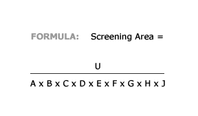
| Screening Area = U ÷ A x B x C x D x E x G x H x J = Square Feet |
| Factor A - Basic Capacity | |||||
| Predetermined rate of material STPH through a square foot of a specified opening when feed to deck contains 25% oversize (Factor B) and 40% half size (Factor C). | |||||
| Surface Square Open | % Open Area | STPH Passing Sq. Ft. | Surface Square Open | % Open Area | STPH Passing Sq. Ft. |
| 4" | 75% | 7.69 | 3" | 74% | 6.17 |
| 3" | 74% | 6.17 | 2 3/4" | 74% | 5.85 |
| 2 3/4" | 74% | 5.85 | 2 1/2" | 72% | 5.52 |
| 2" | 71% | 4.90 | 1 3/4" | 68% | 4.51 |
| 1 1/2" | 69% | 4.20 | 1 1/4" | 66% | 3.89 |
| 1 | 64% | 3.56 | 7/8% | 63% | 3.38 |
| 3/4" | 61% | 3.08 | 5/8" | 59% | 2.82 |
| 1/2" | 54% | 2.47 | 3/8" | 51% | 2.08 |
| 1/4" | 46% | 1.60 | 3/16" | 45% | 1.27 |
| 1/8" | 40% | .95 | 3/32" | 45% | .76 |
| 1/16" | 37% | .58 | 1/32" | 41% | .39 |
| 3 1/2" | 77% | 7.03 | |||
| Factor B - Oversize | |||||||
| Actual % of material in feed to deck that is larger than a specified aperture (Adjusts Factor A to suit conditions). | |||||||
| % Oversize | 5 | 10 | 15 | 20 | 25 | 30 | 35 |
| Factor B | 1.21 | 1.13 | 1.08 | 1.02 | 1.00 | .96 | .92 |
| % Oversize | 40 | 45 | 50 | 55 | 60 | 65 | 70 |
| Factor B | .88 | .84 | .79 | .75 | .70 | .66 | .62 |
| % Oversize | 75 | 80 | 85 | 90 | 95 | ||
| Factor B | .58 | .53 | .50 | .46 | .33 | ||
| Factor C - Half size | |||||||
| Actual % of material in feed to deck that is one-half the size of a specified aperture. (Adjusts Factor A to suit conditions). | |||||||
| % Oversize | 5 | 10 | 15 | 20 | 25 | 30 | 35 |
| Factor B | 1.21 | 1.13 | 1.08 | 1.02 | 1.00 | .96 | .92 |
| % Oversize | 40 | 45 | 50 | 55 | 60 | 65 | 70 |
| Factor B | .88 | .84 | .79 | .75 | .70 | .66 | .62 |
| % Oversize | 75 | 80 | 85 | 90 | 95 | ||
| Factor B | .58 | .53 | .50 | .46 | .33 | ||
| Factor D - Deck Location | |||
| Applies to multiple deck screens. Total screening area is available for top deck separation. Time delay for top deck separation. Time delay for material to pass top deck and 2nd or 3rd decks leaves less effective area available. This factor is expressed in a percent of the top deck effective area. | |||
| Deck | Top | Second | Third |
| Factor D | 1.00 | .90 | .80 |
| Factor E - Wet Screening | |||
| Applies when water is sprayed on the material as it moves down the screening deck. Generally, about 5 to 7 GPM of water are used per STPH of solids fed to the screen. The volume of water required should be supplied so that a portion is combined with the solids into a feed box to prepare a slurry feed to the screen. The balance of water is added through a series of spray bars located over the screening deck. | |||
| Deck | Top | Second | Third |
| Factor D | 1.00 | .90 | .80 |
| Factor F - Material Weight | ||||||||||
| Applies to weights other than 100 lbs. per cu. ft. If bulk density of one cubit foot of material weighs ± 100 lbs. cu. ft., Factor F = lbs. per cu. ft./100. | ||||||||||
| lbs. cu. ft. | 150 | 125 | 100 | 90 | 80 | 75 | 70 | 60 | 50 | 40 |
| Factor F | 1.50 | 1.25 | 1.00 | .90 | .80 | .75 | .70 | .60 | .50 | .40 |
| Factor G - Screen Surface Open Area |
| Applies when open area of screening surface is less than open area shown in Factor A capacity chart. Factor G = %open area of screen surface being used/%open area indicated in capacity chart. |
| Factor G = % Open Area of Surface Being Used ÷ % Open Area of Surface Being Used |
| Factor H - Shape of Surface Opening | |
| Applies when rectangular openings are used. Slotted or oblong openings will pass more material per square foot than square openings. | |
| Square | 1.00 |
| Short Slot (3 to 4 Times Width) | 1.15 |
| Long Slot (More than 4 Times Width) | 1.20 |
| Factor J - Efficiency | |
| Applies when objective screening efficiency is less than 95%. | |
| Square | 1.00 |
| Short Slot (3 to 4 Times Width) | 1.15 |
| 95% | 1.00 |
| 90% | 1.15 |
| 85% | 1.50 |
| 75% | 1.70 |
| 70% | 1.90 |
Screening efficiency is the percent of the undersize in the feed that actually passes the screen surface opening
Factors
DBD = Discharge End Bed Depth
O = Oversize in STPH
C = Cubic Feet Per Ton of Material
5 = Constant
T = Rate of Travel
W = Width of Screening Area in Feet
Efficiency =
% of undersize in feed which actually passes ÷
% of undersize in feed (should pass)
The capacity formula is based on 95% screening efficiency. With the many factors that govern efficient screening, it is impractical to expect a numerical factor in the capacity formula will automatically control this.
The difficult to pass "near size undersize" is most often a controlling factor, and moisture and peculiar particle shapes will compound the problem.
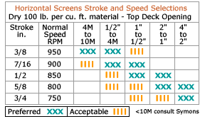
After selecting the proper size and type of screen (inclined or horizontal), it is essential that it operate to produce optimum results - with the best combination of speed, stroke and in the case of inclined screens, slope. Each of these variables has its own effect on the screen performance.
Speed
The frequency at which a vibrating screen operates, usually expressed in revolutions per minute or cycles per minute.
The speed at which the screen is operated should be enough to produce a bed depth that allows stratification to occur before the material is discharged. This gives the fines an opportunity to pass through the screening media. The speed, however, should not be so high that the bearing life is reduced to an uneconomical level. The stroke must be large enough to throw the near size particles out of the aperture before they have a chance to adjust themselves and pass through.
Stroke
The distance between extremities of traverse: viz, the diameter of a circular motion.
The stroke must be large enough to throw the near size particles out of the aperture before they have a chance to adjust themselves and pass through. Too much stroke will tend to increase the distance a particle is thrown and as a result, reduce the effective life of the screen. Too large a stroke also has a tendency to affect the life of the screening surfaces as well as the screen body parts and mechanism.
Slope
The angle with the horizontal made by the first or top deck screen section.
The slope of inclined screens must be sufficient to keep the material moving across the deck, and yet not so steep that it foreshortens the opening too much and interferes with the passage of the material through the deck. In most instances, the slope of the screen should be steeper for counter -flow rotation than for with-flow rotation.
In general, a lesser slope will increase the depth of the bed of material on a deck. This increase in load of a deck will increase screening media wear and also produce more plugging. In extreme cases the load can become so great the screen will bog down. Conversely, a steeper slope will have the same affect as too large a stroke. It will increase the distance between impacts on a screen for a given particle and reduce the effective length of the screen.

